1 Introduction
Ultrasonic flow detection technology makes it possible to measure the velocity of the flow by modulating the velocity of the ultrasonic waves of the fluid being measured. In recent years, with the advent of digital signal processing technology, large-scale digital circuits and the emergence of new types of ultrasonic transducers, ultrasonic flow detection technology has made great strides. Compared with the traditional flowmeter, the ultrasonic flowmeter solves the problems of large diameter, large flow, and difficulty in measuring the flow of all kinds of open and underflow liquids. At the same time, it can measure liquids, gases, and even liquids of two-phase media. Flow, no requirement for measuring medium. With the advantages of low pressure drop, low energy consumption and high measurement accuracy, it is gradually replacing the mechanical flowmeter. However, when ultrasonic waves are used for small-diameter flow measurement, because the time for the ultrasonic wave to pass through the measured liquid is very short, useful measurement signals are easily submerged by clutter, which affects the measurement accuracy of the flow rate. For the above problems of small-diameter ultrasonic flow detection, through the improvement of hardware circuit design and software algorithms, the problem of measurement accuracy is solved.
2 Ultrasonic flowmeter transducer drive and signal processing
Ultrasonic flow meter detection methods mainly include: time difference method, Doppler effect method, correlation method, noise method, beam offset method, etc. The time difference method ultrasonic flow depends on the ultrasonic signal propagated to the medium, in the flowing medium will With the medium flow velocity information, the ultrasonic echo sensor receives the ultrasonic echo signal with the flow velocity information to the circuit board by means of the ultrasonic receiving sensor, and after a series of signal processing, the measured flow rate or flow rate of the medium is obtained.
(1) How the time difference method ultrasonic flow meter works
The key to time difference method measurement is to be able to obtain high-precision time measurement parameters. In recent years, with the continuous appearance of high-speed time counting processing chips, measurement accuracy of tens of picoseconds has become possible, which is used for small aperture for time difference method. Ultrasonic flowmeters provide metering assurance. Figure 1 shows the basic principle of time-difference ultrasonic flow measurement.
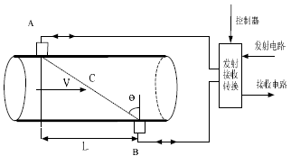
Figure 1 principle of ultrasonic flow measurement
The two ultrasonic probes A and B can both transmit and receive. When the probe A is transmitted and the B receives, the ultrasonic wave propagates in the fluid in the downstream, and the speed of the ultrasonic wave is accelerated to measure the forward flow time; Speed ​​will slow down.
In the time difference method, the downstream propagation time t1 is:

The countercurrent propagation time t2 is:

The time difference Δt between the forward and backward flows is:

Available:

Where C is the speed of sound of the ultrasonic wave in the liquid; L is the distance between the two transducers; V is the average flow velocity in the direction of the central axis of the pipe; θ is the incident angle of the ultrasonic wave into the liquid; Additional time.
(2) Drive control of ultrasonic transducer
In the ultrasonic flow measurement, the transducer is first driven, and the excitation transducer generates oscillation and emits an ultrasonic signal. The following is the excitation of the transducer using one drive pulse, ten drive pulses, and fifteen drive pulses, respectively. Source, Fig. 2 is the waveform received by the transducer at the receiving end during 1 drive pulse. It can be seen that when a pulse is driven, the received waveform is relatively weak and the waveform is very irregular. Figure 3 shows the waveforms received by the receiver transducer when there are 10 drive pulses. The shape of the waveform is significantly improved. Figure 4 shows the waveforms received by the receiver transducers for 15 drive pulses.
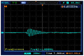
Figure 2 1 drive pulse receiving wave
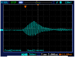
Figure 3 10 pulse reception waveform
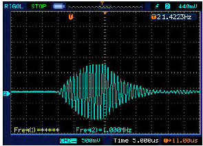
Figure 4 15 pulse reception waveform
It can be seen from the above several graphs that when the 15 pulses are received, the waveform received by the transducer is a more standard sine wave, and the amplitude is larger. The GP2 can emit a maximum of 15 driving pulses. Therefore, 15 driving pulses are selected.
The scientific name of the PVC material of the inflatable product is polyvinyl chloride, abbreviated as PVC. The inflatable castle is a large inflatable toy for children. The materials generally used in children's Inflatable Toys are high-polymer fiber double-layer weaving and PVC coating. This is a high-strength air-tight cloth or PVC air-tight cloth with a mesh. The thickness of the cloth is generally: 0.45-0.8 mm.
The characteristics of this material are:
1. It has strong tensile force and strong tear resistance.
2. Strong anti-fouling ability, the surface can be kept clean for a long time and easy to clean.
3. Strong anti-fracture ability, the surface is not easy to open glue.
4, and strong anti-corrosion, not easy to oxidize.
5. High temperature and low temperature resistance, can be used at minus 28 degrees and high temperature above 30 degrees.
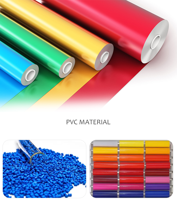
Pvc Material,Pvc Film,Pvc Film Roll, Rigid Pvc
P&D Plastic Manufacture Co., Ltd , https://www.jminflatablepool.com