Design and calculation of a new type of hollow hydraulic force feedback heavy oil pump for petroleum machinery design and its structural optimization design Cui Zhijian12 Hu Hongping2 Jiang Shunong3 Chen Ziguang3 Hu Yuantai23(1.School of Petroleum Engineering, Xi’an Shiyou University2. Department of Mechanics, Huazhong University of Science and Technology3 Central South University Mechanics and Sensing Technical Institute) feedback, hollow sucker rods and powerful open and close plungers and many other advantages. The structure optimization method that maximizes the actual pumping quantity is proposed. This method is used to optimize the matching design between the diameter of the feedback pump pump barrel and the working pump cylinder diameter of the heavy oil pump, so that the maximum pumping pump outer diameter can be fixed. The actual pumping volume is the largest. Theoretical analysis and numerical calculations show that the new type of hollow hydraulic force feedback heavy oil pump greatly improves the theoretical displacement compared with ordinary oil pump; for different pump pump cylinder diameters, the optimal feedback pump pump cylinder diameter is matched to make single stroke The actual pumping volume reaches the maximum.
The feedback pump cylinder diameter and working pump cylinder diameter have been optimized. Due to the high viscosity of heavy oil and high flow resistance, when the heavy oil is pumped by a conventional pump, the difficulty of the sucker rod column and the eccentric wear of the rod tube often occur. It is difficult for the heavy oil to enter the pump, the fullness coefficient of the pump is low, and the valve ball is closed and lags behind, resulting in a low pump efficiency and affecting the production efficiency of the oil well. A new type of hollow hydraulic force feedback heavy oil pump (hereinafter referred to as the new heavy oil pump) was designed to solve the problems often encountered in the extraction of heavy oil. The structural and hydraulic feedback working principle structure of the new heavy oil pump structure is shown. The hollow sucker rod runs through the entire oil extraction pipeline, the heating cable is in the hollow sucker rod, and the hollow sucker rod forms a heating loop.
2 How the hydraulic feedback works The space between the feedback plunger and the working plunger is called the working chamber.
On the upstroke, the hollow sucker rod drives the feedback plunger and the working plunger to move upward. The distance between the two plungers does not change. Since the diameter of the feedback plunger is smaller than the working plunger, the working chamber volume decreases and the pressure increases. Large, the moving valve is closed, and the feedback valve and the feedback plunger are forcibly opened. The liquid in the pump is discharged into the oil pipe through the feedback valve until it reaches the ground.
On the down stroke, due to the frictional force, the downward movement of the feedback plunger due to gravity lags behind the hollow sucker rod, and part of the oil flow can still enter the upper part of the pump through the feedback plunger. Until the hollow sucker rod drives the feedback valve downward, the feedback valve and the feedback plunger are forcibly closed. The thick oil above the feedback piston forms the liquid column pressure and acts on the feedback plunger to generate a downward pulling force on the sucker rod ( That is, hydraulic feedback), which solves the problem of the difficulty of the sucker rod downwards and the eccentric wear of the rod tube. At the same time, the working chamber volume increases, and due to the larger diameter of the working plunger, the pressure reduction is relatively large. Under the action of sunken pressure, the traveling valve opens and the oil flow enters the working chamber smoothly, solving the difficult problem of pumping heavy oil.
It should be noted that the feedback valve and the working valve in the working pump cylinder have different forms of opening and closing. The former is forced to open and close between the hollow sucker rod and the feedback plunger.
The new heavy oil pump combines the advantages of a powerful open-close plunger, a hollow sucker rod and hydraulic feedback suitable for heavy oil production.
The feedback valve of the hollow suction pump is mechanically forced to open and close11, which can prevent air lock and increase the flow area, thereby reducing the resistance of the liquid passing through and improving the pump efficiency.
When the working plunger goes up, due to the difference between the diameters of the feedback plunger and the working plunger, the pressure in the working chamber is large, which is beneficial to the upward movement of crude oil, and the pumping efficiency of the working chamber is increased. 121. The pressure of the liquid column in the tubing during the downstroke On the feedback plunger, a downward pulling force is generated on the hollow sucker rod, so that the sucker rod string is in a tensioned state during the downward process, thereby solving the difficult problem of sucker rod string down in the heavy oil well and effectively preventing The sucker rod bends to reduce the stroke loss and eccentric wear of the rod tube and improve the pumping efficiency. 12. At the same time, due to the difference between the feedback plunger and the working plunger diameter, the difference between the pressure in the working chamber and the pump sinking pressure increases, which overcomes the heavy oil. Difficulties in pumping.
The use of hollow rod over-pump (or over-pump) electric heat recovery technology enables the whole process of oil production from the pump, pump, and pump to be conducive to the recovery of heavy oil and high-condensation oil. 131. No action string, By injecting the heat carrier and the viscosity reducer under the pump through the hollow sucker rod, the viscosity of the crude oil is reduced. The hollow sucker rod can also perform downhole testing and inject steam into the thick oil layer to implement the steam stimulation process 111. Performance analysis and structural optimization The equivalent diameter of the new heavy oil pump is equal to 38.10 mm, the substituted elastic modulus, and the lower pump depth , D equivalent pump diameter, m. The impact of inertial load on the stroke of the piston. Therefore, the ratio of the theoretical displacement of the HLB and the new heavy oil pump is the equivalent of the HLB type pump. The diameter is 71994-201 ChmaAcSei The working plunger stroke is considered after static and dynamic loads. The pump efficiency under load is the degree of influence of the gas on the pump efficiency. It is expressed by the fullness factor å©, R is the ratio of the gas to oil in the pump, and k is the remainder. Gap ratio, so the pump efficiency n under the gas is such as neglecting the influence of the leakage, the actual pumping quantity of the single stroke is the same as the polished rod stroke, and only the actual pumping quantity of the single stroke of the oil pump is calculated and compared. From the above derivation, we can draw the following conclusion: In the case of a fixed operating pump cylinder diameter D2 of two 105mm, under different pump air-oil ratio, the actual pumping amount of a single trip is shown in the curve of the pump cylinder diameter of the feedback pump.
The actual pumping volume of the single stroke of the pump cylinder diameter under different working pump diameters is plotted with the diameter of the pump cylinder of the feedback pump as the diameter of the pump cylinder, and the actual pumping volume per stroke is the curve of the pump cylinder diameter of the feedback pump. It can be seen from the figure that for different working pump pump barrel diameters, different feedback pump pump barrel diameters should be selected to match the optimal value so that the single stroke actual pumping quantity reaches the maximum.
From equation (5), the smaller the pump cylinder diameter of the feedback pump is, the larger the theoretical oil production per stroke is. At the same time, it can also be known that the larger the stroke loss, the smaller the efficiency of the load pump, and the smaller the actual stroke of the working plunger is, the smaller the actual stroke of the single stroke is. It can also be seen that there is an optimal feedback pump cylinder diameter that maximizes single stroke pumping. In the figure, the inner diameter of the inner diameter of the feedback pump cylinder is D1=50mm, the maximum single-stroke pumping volume is 2.26×10⁻²m3, and the greater the gas-oil ratio R in the pump, the smaller the D1 should be. Therefore, when the pump cylinder diameter of the working pump is the same, the diameter of the pump cylinder of the feedback pump can be optimized to maximize the pumping volume.
Concluding remarks It is an effective method to extract heavy oil by adopting a mechanical forced opening and closing valve, hydraulic feedback, hollow sucker rod, current or steam heating viscosity reduction and viscosity reduction agent viscosity reduction. At the same radial size, the new heavy oil pump greatly increases the theoretical displacement compared to ordinary oil pumps. Through structural optimization, the diameter of the feedback pump cylinder can be matched with the pump cylinder diameter, so that the maximum pumping volume can be achieved.
CNC punching and shearing equipment for the processing of angles studied for small and medium size steel construction companies. These lines provide flexibility and simple use, and are characterized by an innovative infeed roller conveyor system allowing high precision with minimum loss of material.
Advantages:
- Versatile solution: each model can be configured according to the most diverse production lots and to customer requirement with an affordable investment.
- Compact frame for easy installation and reduced overall size.
- Remote diagnosis is possible through a network connection that allows our service team to perform routine checks
The linear tool carrier (y-axis) has several stations that hold the punching tools and one cutting tool. Especially for flexibility and efficient processing are setup times a crucial cost factor. Downtimes should be reduced to a minimum. Therefore, recent tool systems are designed for fast and convenient change of punches and dies. They are equipped with a special plug-in system for a quick and easy change of tools.
There is no need to screw anything together. The punch and die plate are adjusted to each other automatically Punches and dies can be changed rapidly meaning less machine downtime

Angle punching round hole and s-lot hole samples
The Punching Unit:
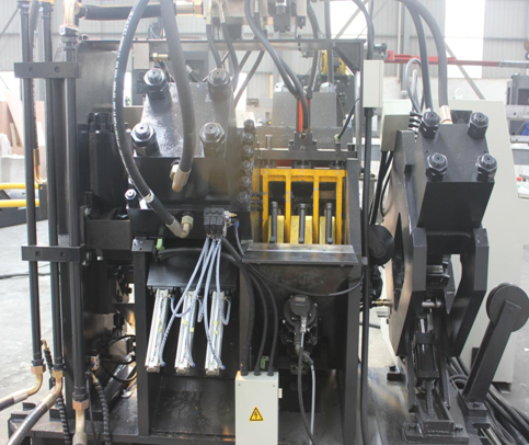
This
unit is consists of three pieces of machine body, two hydraulic pressure
punching cylinders, four die bases with upper and lower dies, and two sets of
servo systems for controlling stadia adjustment. This unit can be installed three
different standards punches on each side. Every punch matches with one gas
cylinder. The gas cylinder piston pole links a padding block, which installed
between punch poles and oil cylinder press head. It automatic chooses punch,
namely choose relevant gas cylinder to drive relevant padding block according
to the order of computer. The position of stadia is located by servo motor,
which drives ball screw to drive die base move up and down, thus to achieve the
requirement of stadia position. It can punch many rows and different diameters
holes on two wings of angle steel.
The Marking Unit:
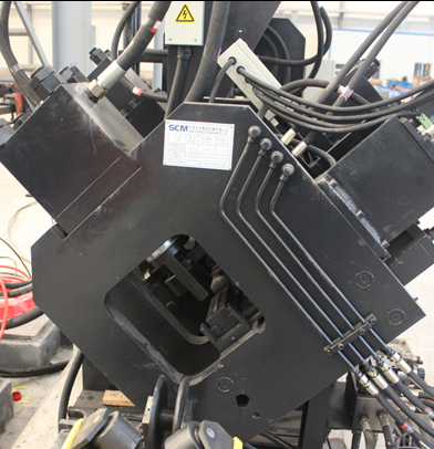
New design for type marking unit, more stable and longer life
This
unit consists of fix lathe bed, movable lathe bed, hydraulic pressure head,
four positions oil cylinders (can change four positions for character boxes)
and adjusting device. According to the order of computer, to mark on places the
drawings require. For making the mark clear and endurable, and avoiding the
angle steel abrade character heads, it adds oil cylinder of movable lathe bed
uplift and falling. For satisfying the processing scope, it adds manual
adjustment setup, which can change the position of characters to adapt
different standards angle steel.
The Shearing Unit:
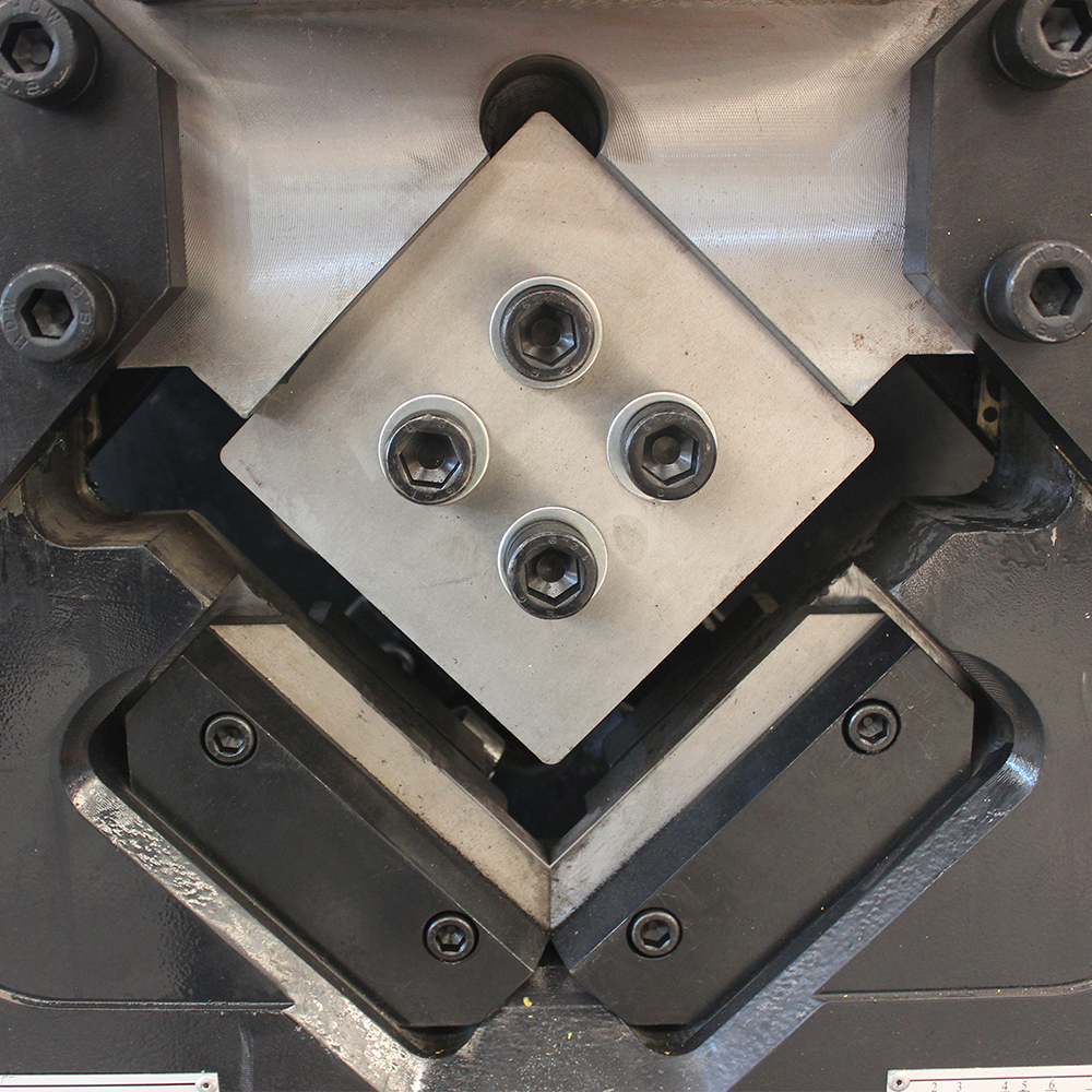
This unit consists of frame
machine body, hydraulic pressure dynamic cylinder, upper blade setup, lower blade
setup, and front bracket tank etc. The front bracket tank avoids angle steel to
strike lower blade. The lower blade setup can adjust the clearance according to
angle steel thickness to ensure the cutting quality. It cuts different
standards of angle steel, according to the order of computer.
The Feeding Conveyors:
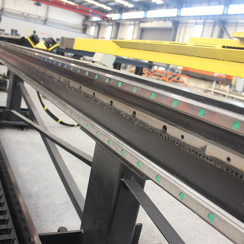
Double linear guide and detection rack for total
feeding conveyor ensure better accuracy and machine stability. Linear guide
from Taiwan HIWIN.
The NC Feeding Carriage:
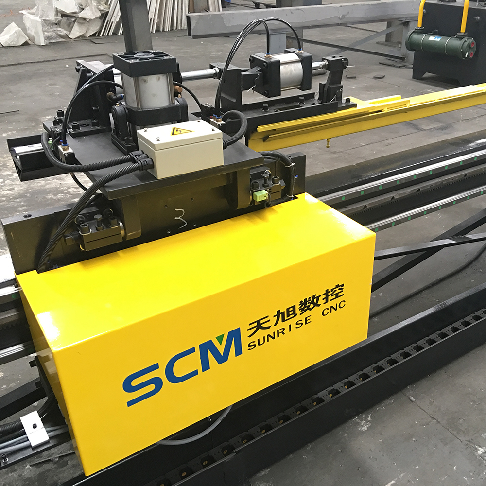 Newest NC carriage, linear guide drive, accuracy
and stability much better!
NC carriage linear guide cushion, pneumatic lift
Work Table And Overturning Rack:
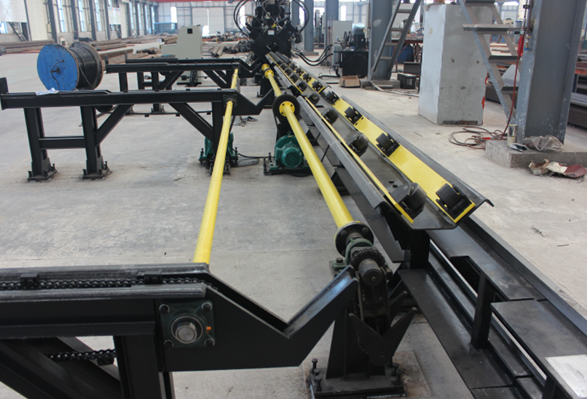
Overturn
rack for loading material automatically
Angle Punching Marking Shearing Line
Angle Punching Marking Shearing Line,Angle Connecting Plate Punching,Punching Shearing And Marking Line,CNC Angle Production Line
Shandong Sunrise CNC Machine Co., Ltd , https://www.scmcnc.com