Xu Shuang
Ankerui Electric Co., Ltd. Â Â Â Jiading 201801
1 Subway Energy Consumption Analysis
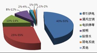
The metro is a large-capacity urban rail transit system, and it is also a large consumer of electricity. The main form of energy consumption during subway operation is electrical energy. According to the statistical analysis of the electricity load on the subway, the energy consumption is mainly distributed in the traction power consumption of trains and various power lighting equipment, such as ventilation and air conditioning, escalators, lighting, and weak electrical equipment. Figure 1 shows the distribution of energy consumption in the various subway systems.

Figure 1 Distribution of energy consumption of various subway systems
It can be seen from Figure 1 that the percentage of electricity used by traction and various power lighting of subway trains is about 50% each. The energy consumption of traction power supply, ventilation and air conditioning, escalators, lighting, etc. accounts for about 90% of the total energy consumption of the metro, which is the focus of energy conservation. Therefore, it is necessary to strengthen energy management and monitoring for major power equipment in metros and heavy-capacity equipment that is continuously operating, and to perform economic and technical assessment and comparative analysis of equipment that uses frequency conversion and other energy-saving technology measures.
2 Feasibility Analysis of Subway Energy Management System
At present, the integrated monitoring system has been successfully applied in urban rail transit projects around the world, and has brought about good economic and social benefits. The integrated monitoring system is a large-scale integrated automation system. It uses a common software platform, a consistent hardware architecture, and a unified human-machine interface. Through the integration and interconnection of related systems, a highly-shared information platform has been established to implement subways. Information sharing and resource sharing between systems improves the efficiency of day-to-day management and dispatch operations and the overall service level of subway operations.
In addition, domestic low-voltage distribution cabinets and environmental control cabinets for newly-built subways have adopted smart switchgear design solutions. The intelligent network in the low-voltage power distribution cabinet and the environmental control cabinet is composed of smart meters in the cabinet through the redundant field bus. At the same time, the intelligent communication manager uploads the data information to the integrated monitoring system. Using this method not only can ensure that the collected equipment energy data can be sent to the monitoring system in time, but also has high reliability, simple system configuration, economy, and easy centralized management.
The infrastructures such as the industrial Ethernet network of the comprehensive monitoring system of the metro and the underlying field bus architecture have created very favorable conditions for the implementation of the energy management system. On this basis, using advanced and reliable energy management software and hardware, a complete and advanced metro energy management system can be established.
3 The Application of Subway Energy Management System in the Anting Station Lot of Rail Transit Line 11
3.1 Project Overview
Anting Station is located at Moyu Road, Cao'an Road, Anting Town, Jiading District, Shanghai. It is an elevated island station on Shanghai Rail Transit Line 11 and was opened on March 29, 2010. Design and construction of Metro Line 11 energy management system of Shanghai Anke Rui Electric Co., Ltd. to undertake in August 2011. The remote monitoring of the high-voltage, low-voltage incoming line, capacitance compensation, contact and outlet loops in the power distribution room was realized. Acrel- 5 000 reserved for the energy management system expansion interface, it can be easily expanded. Â Â Â Â Â Â Â Â Â Â Â Â Â Â Â Â Â Â Â Â Â Â Â Â Â Â Â Â Â Â Â Â Â Â Â Â Â Â Â Â Â Â Â Â Â Â Â Â Â Â Â Â Â Â Â Â Â Â Â Â Â Â Â Â Â Â Â Â Â Â Â Â Â Â Â Â Â Â Â Â Â Â Â Â Â Â Â Â Â Â Â Â Â Â Â Â Â Â Â Â Â Â Â Â Â Â Â Â Â Â Â Â Â Â Â Â Â Â Â Â Â Â Â Â Â Â Â Â Â Â Â Â Â Â Â Â Â Â Â Â Â Â Â Â Â Â Â Â Â Â Â Â Â Â Â Â Â Â Â Â Â Â Â Â Â Â Â Â Â Â Â Â Â Â Â Â Â Â Â Â Â Â Â Â Â Â Â Â Â Â Â Â Â Â Â Â Â Â Â Â Â Â Â Â Â Â Â Â Â Â Â Â Â Â Â Â Â Â Â Â Â Â Â Â Â Â Â Â Â Â Â Â Â Â Â Â Â Â Â Â Â Â Â Â Â Â Â Â Â Â Â Â Â Â Â Â Â Â Â Â Â Â Â Â Â Â Â Â Â Â Â Â Â Â Â Â Â Â Â Â Â Â Â Â Â Â Â Â Â Â Â Â Â Â Â Â Â Â Â Â Â Â Â Â Â Â Â Â Â Â Â Â Â Â Â Â Â Â Â Â Â Â Â Â Â Â Â Â Â Â Â Â Â Â Â Â Â Â Â Â Â Â Â Â Â Â Â Â Â Â Â Â Â Â Â Â Â Â Â Â Â Â Â Â Â Â Â Â Â Â Â Â Â Â Â Â Â Â Â Â Â Â Â Â Â Â Â Â Â Â Â Â Â Â Â Â Â Â Â Â Â Â Â Â Â Â Â Â Â Â Â Â Â Â Â Â Â Â Â Â Â Â Â Â Â Â Â Â Â Â Â Â Â Â Â Â Â Â Â Â Â Â Â Â Â Â Â Â Â Â Â Â Â Â Â Â Â Â Â Â Â Â Â Â Â Â Â Â Â Â Â Â Â Â Â Â Â Â Â Â Â Â Â Â Â Â Â Â Â Â Â Â Â
   The entire system adopts a network distributed structure. The monitoring host is located in the duty room of the monitoring center (located in the central power distribution room). The system adopts an open communication protocol, and is connected to the high and low voltage distribution system through RS-485 field bus to realize data communication. Function .
3.2 Network Structure
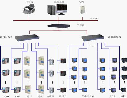
The system mainly adopts a hierarchical distributed computer network structure. As shown in Figure 2, it is divided into three layers: station control management layer, network communication layer and field device layer.

Figure 2 Network structure
The field device layer is mainly connected to various types of meters and protection devices used for the collection and measurement of electrical parameters in the network, and it is also a necessary basic element for constructing the distribution system. The project includes M5 series comprehensive protection, ACR series network instruments and WHD series temperature and humidity controllers, which realize the monitoring and management of 407 field devices.
The network communication layer is composed of a communication server, an interface converter, and a bus network. This layer is a bridge for the exchange of data information.
The station management layer is the management personnel for the distribution network, and this layer directly faces the users. This layer is also the uppermost part of the system. It is mainly composed of energy management system software and necessary hardware equipment such as computers, printers, and UPS.
3.3 Device Parameter List
name
Model, specification
unit
Quantity
Note
Field device layer
Electricity meters, etc.
 
only
407
 
Station control management
Workstation host
RPC-610 Core2 2.8G/2G/500G + Keyboard
station
1
North China Industrial Control
monitor
19W "LCD Monitor
station
1
AOC
UPS power supply
MT1000
station
1
SANTAK
printer
A4 format
station
1
 
Console
Steel wood structure with a chair
set
1
Shanghai Xiangming
Energy Analysis Software
System Configuration Software Acrel-5000
set
1
Ankerui
Energy Analysis Software
Data Storage Software Acrel-dbSQL
set
1
Ankerui
Energy Analysis Software
Energy Management Software Acrel-EnerSys
set
1
Ankerui
Energy Analysis Software
Device Driver Software Acrel-Driver
set
1
Ankerui
Energy Analysis Software
Report Analysis Software
set
1
Ankerui
Energy Analysis Software
Environmental monitoring software
set
1
Ankerui
Network communication layer
Industrial network switch
D-LINK 8 port
station
1
D-LINK
Industrial Serial Server
NPORT5630-16 RS485 interface × 16
set
2
MOXA
3.4 System Design Parameters
Telemetry accuracy rate:
≥99.9%
Analog measurement error:
<0.5%
Telemetry update period:
15min (minimum resolution 1min adjustable)
Call screen response time:
<2S
Accident push screen time:
<2S
Network rate:
10M/100M
Working environment temperature range:
-20 °C ~+55 °C
Relative temperature:
≤95% (25 °C )
Historical curve daily, monthly report storage time
≥1 year
System service life:
≥5 years
MTBF: MTBF:
≥30000 hours
3.5 System Functions and Software Interface
3.5.1 Statistics of Classification and Item Energy Consumption
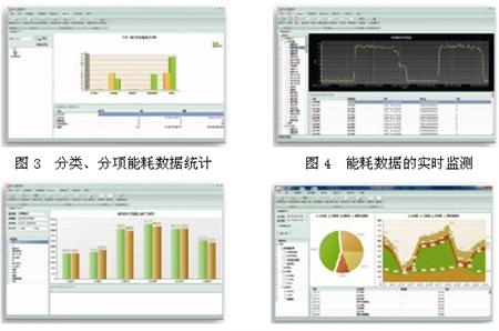
The system has the storage function of historical data, alarm information, etc. The storage history data is saved for more than three years. The system also has the function of sending classified and itemized energy consumption data to higher-level data centers according to the requirements of "energy data that needs to be sent to the upper-level data center." The interface is shown in Figure 3.
3.5.2 Real-time monitoring of energy consumption data
The system has a good openness, can expand the function of the user's requirements, and customize the personalized report and analysis template for the user based on the basic analysis function; the system has an alarm management function, responsible for the transmission of alarms and events, alarm confirmation and alarm recording Function to inform the user or for user inquiries; the system has rights management, system log and system parameter settings and other functions. The interface is shown in Figure 4.
3.5.3 Analysis of the same-ring and ring-to-loop ratio of energy use
Monthly, year-on-year or quarter-by-month analysis of energy consumption (standard coal or kilowatt-hours) and energy consumption per unit area (standard coal or kilowatt-hours) for each category, sub-item, etc. It can preset, display, query and print the statistical report of energy consumption of common buildings. The interface is shown in Figure 5.
3.5.4 Analysis of Building Energy Consumption Data
After collecting and summarizing classification and itemized energy consumption data, the system can generate various data charts, pie charts, and bar charts, and reflect and compare the values, trends, and distributions of collected data and statistical data in real time. The system can be summarized daily, month by month, year by year based on total energy consumption and energy consumption per unit area, and displayed, searched, and printed in various forms such as coordinate curves. The interface is shown in Figure 6.
3.5.5 Remote Network Access Function
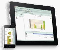
After the system is published on the Web, remote network access is available. Based on the .Net platform, it is developed using ASP.Net and JQuery technology and can be accessed through the Internet. It has cross-platform features and users can access it through various mobile terminals (notebooks, tablet computers, mobile phones, etc.). The interface is shown in Figure 7.

Fig.5 Analysis of the same and ring ratio of the energy consumptionFig.6 Analysis of building energy consumption data

Figure 7 Remote Network Access Function
4 Conclusion
“Only those that can be measured can be managed.†The overall goal of the metro energy management system is to establish an energy management system for a fully linear or entire urban rail transit network and build a power luminaire that covers the train traction power and each station. Electricity, as well as automatic monitoring systems for energy media, fuel gas, tap water and other energy media in the depot. While satisfying the needs of public transportation functions, the subway should promote the application of advanced energy-saving technologies and strengthen energy-saving management and energy-consumption control in accordance with the principles of rational energy use, in order to increase energy efficiency and reduce operating costs.
references
[1] GB50157-2003 Metro Design Specification [S].
[2]JGJ16-2008 Civil Building Electrical Design Specification [S].
[3] Shanghai Ankerui Electric Co., Ltd. Product Manual. 2013.01.
About the Author:
Xu Shuang, female, undergraduate, Ankerui Electric Co., Ltd., the main research direction for the smart grid power distribution, Email: Mobile QQ
"Atlas of Design and Application of Building Energy Consumption Monitoring and Management System" (atlas number: ACR12CDX301) edited by Ankerui Electric Co., Ltd. and Shandong Construction Electrical Technology Information Network, this atlas combined with Acrel-5000 energy consumption The monitoring system complies with the electrical design specifications and meets the requirements for the construction of energy-saving supervision systems for office buildings and public buildings of state agencies, to achieve the scientific and data-based management of green building energy use, and to achieve the goal of saving energy and reducing consumption of green buildings. The Atlas is applicable to the system design, construction, operation and maintenance of energy monitoring and management of office buildings and public buildings of newly-built or rebuilt national offices. If you need atlas, please provide your organization's name, department, address, zip code, contact person, contact telephone number, email address, fax 021-69155331, mail or QQ to Ankeru Xu cream engineer, Ankerui Electric will give you a free gift. .
Ball Mill Liner,Liner Plate Ball Mill Spare Parts,Liners Industrial Ball Mill Plate,Mill Liner Mill Spare Parts
Wuyi Slon Machinery Co.,Ltd , https://www.slonmachinery.cn