The spiral unfolding indicates that the helical gear has a spiral lead along the axis and must rotate about the axis 2, that is, ptan=d(1) where d gear indexing circle diameter 2 helical gear machining Simulated milling cutter modeling uses a disc-shaped milling cutter to machine spur gears. The disc-shaped milling cutter is cut as shown. The axial cutting of the milling cutter is the same as that of the gear end face, but when machining the helical section of the milling cutter, the milling cutter The contact line of the helical gear profile is a spatial curve, and the shape of the curve is related to the gear parameters and the diameter of the milling cutter.
Therefore, the axial section of the milling cutter is not equal to the normal tooth profile of the helical gear and should be derived by mathematical formula.
The equation for the involute helicoid is known as: x = rbcos(0 u ) rbusin(0 u )y=rbsin(0 u )-rbucos(0 u )z=p whose normal component is: nx=prbusin( 0 u )ny=-prbucos(0 u )nz=r2bu and the vector conditional expression of the contact line on the helicoid surface is: (kR)n=0 and then the relationship of the helicoid surface: nxy-nyx=pnz (joint The equation of the contact line is: znx Lcotny (Lx pcot)nz=0 to find the contact line equation in (ox, y, z) coordinates, and then transform the contact line to (oX, Y) by coordinate transformation. In the Z coordinate system, the positional relationship of the two coordinate systems is as shown, and the axial section of the tool is obtained: R=X2 Y2Z=dtan
The position relationship between the tool and the workpiece is selected according to the tooth shape of the workpiece. The corresponding values ​​are obtained by the formula, and then they are paired into the formula to obtain the (R, Z) values ​​of a series of tools. As the discrete points of the tool, as shown, for the gears with different modulus and different number of teeth, the milling cutter can be designed by the above method.
AutoLISP for milling process simulation In the AutoCAD2000 Chinese drawing interface, select the tool in the drop-down menu (T) AutoLISP(S)VisualLISP Editor (V), or type vlide at the command prompt Command: to enter VLISP Integrated development environment. Create a new file, select the file (F) New File (N) menu or press Ctrl N, then edit the program in an empty text editor and save.
After the program is programmed, it can be called directly under AutoCAD. The method is: select the tool (T) AutoLISP (S) in the drop-down menu to load (L), and then double-click the name of the program you just saved to load the program. Enter the function name in the command prompt to run the program, input the parameters as prompted, and realize the helical gear machining simulation.
When the development of the helical gear simulation machining program is completed by using the AutoLISP language, the built-in commands of the CAD are called, so that the programming is simple and the operation is convenient, and the simulation results are compared with the actual measurement, and the error is small.
We have 16 years' experience producing and exporting aluminum materials.
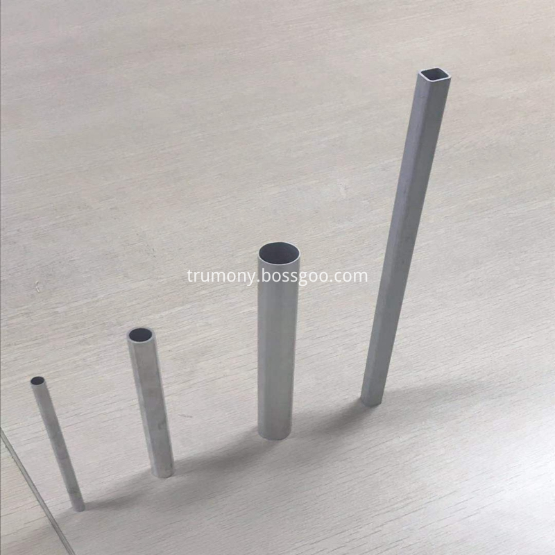
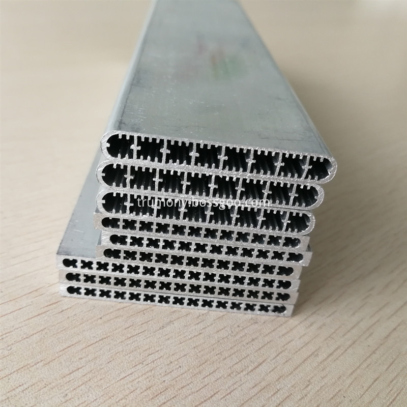
Aluminum tube is one of our strong product. It has many different kinds of aluminum pipe. Such as aluminum round tube, aluminum extruded tube, high frequency welding tube, micro channel multi-port tube, aluminum oval tube. Aluminum tube is widely used in many applications such as automobile industry, industry cooling industry. construction industry. Trumony has advantage in making Aluminum heat pipe, aluminum extruded tube, aluminum high frequency welding tube and manifolds.
Trust in harmony,we care what our clients care.


Aluminum Pipe, Aluminum Tubing, China Aluminum Pipe, Aluminum Pipe supplier,heat pipe supplier,high frequency welding tube,micro channel multiport tube
Trumony Aluminum Limited , https://www.szaluminumpipe.com